What the result should look like
At the end of commissioning you should have more than saved settings. You should have a working system: the web interface opens, the chosen network works, time is correct, Modbus lines are configured, the required devices are visible, and current values appear on screen.
The right order of work
A common mistake is trying to do everything at once: MQTT, scenarios, gateway, manual imports, and advanced options, before basic communication has even been confirmed. A simpler sequence is much safer.
flowchart TD
    A[Power on the gateway] --> B[Open the web interface]
    B --> C[Log in]
    C --> D[Choose operating mode]
    D --> E[Set network]
    E --> F[Set time]
    F --> G[Configure Modbus lines]
    G --> H[Find or add devices]
    H --> I[Verify live values]
    I --> J[Move into daily operation]
Starting point: an empty gateway
A new or reset gateway is only a reachable web device at first. Field communication has not been proven yet: lines may be unconfigured, the device list may be empty, and Control is not expected to show values. Commissioning therefore moves from interface access to local Modbus proof, not the other way around.
The top status row and the runtime block in Settings show actual state. A saved setting alone does not prove that the service is already working: check runtime state, device responses, and value freshness.
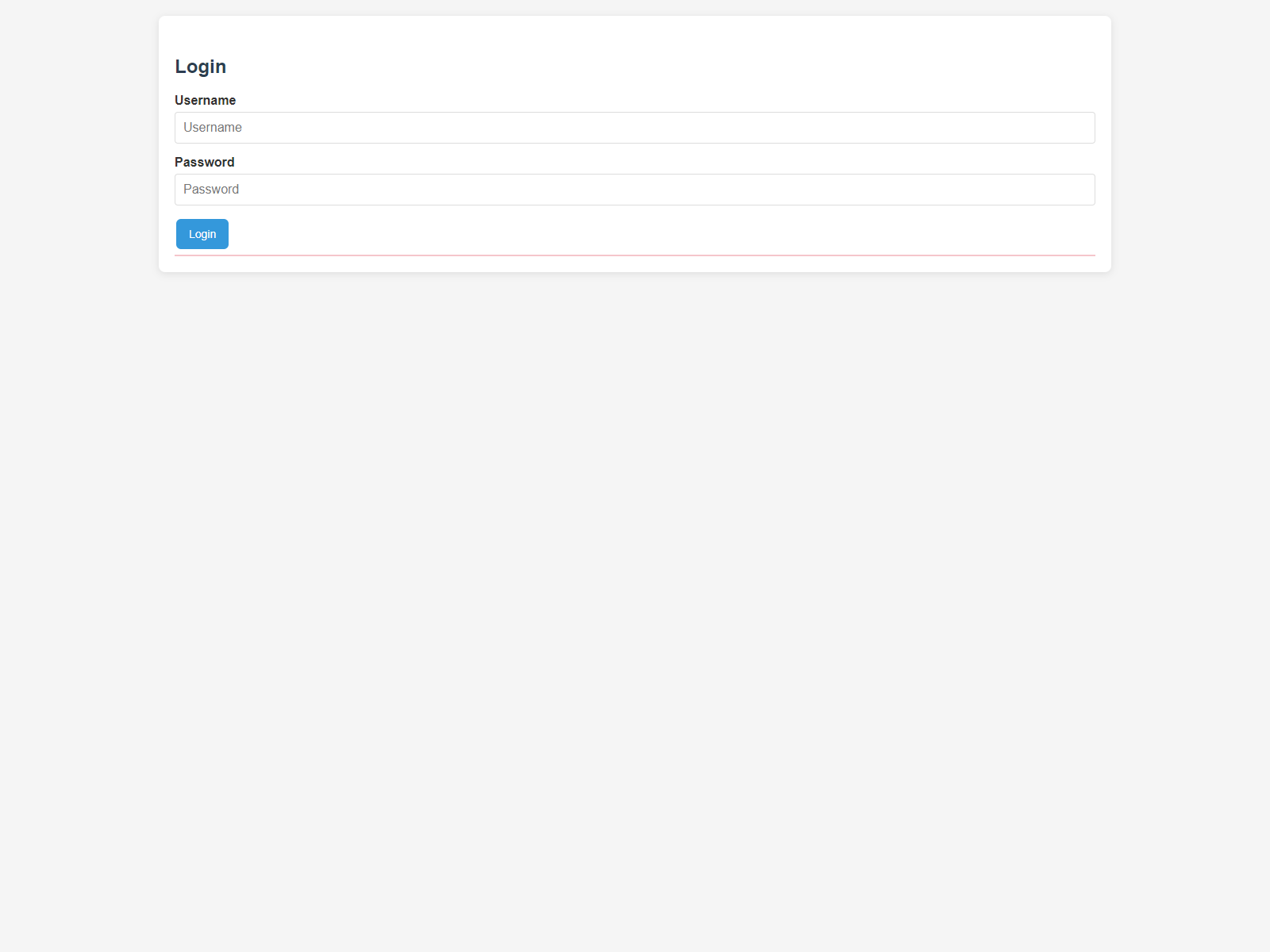
Step 1. Confirm that you can actually reach the device
The first task is simple: open the local web interface and log in. Until that works, everything else is secondary.
If login does not work, solve that first by checking network access, credentials, and the basic availability of the controller.
Step 2. Choose the operating mode
Operating mode defines how the gateway should behave toward the outside world. The practical question is simple: should the device work with UMEC Space IoT Cloud, connect to an outside MQTT server, or stay fully local for now. For the platform route, use the UMEC Space guide and UMEC Space Dashboard.
UMEC_SPACEfor operation with UMEC Space IoT Cloud.MQTT_GENERICfor operation with an outside MQTT server.MQTT_DISABLEDfor local-only use without an external cloud path.
The selected mode defines the later completion path, but it does not replace local Modbus verification. Even if the cloud or broker is already configured, prove that line, device, and values work locally first.
Step 3. Set the network
After choosing the operating mode, the next task is the network. The gateway may use Wi-Fi, Ethernet, or both, and the user needs to understand which interface is expected to be primary on the site.
Wi-Fi
Useful where wired networking is unavailable or where Wi-Fi is already the accepted communication path.
Ethernet
Usually preferred for fixed cabinets because it is more predictable in industrial environments.
Failover
If both interfaces are used, the user can define which one is primary and how switching should work during communication loss.
Step 4. Set the time
Time is not a cosmetic detail. Logs, scenarios, and event history depend on it. If time is wrong, later troubleshooting becomes much harder.
That is why timezone, NTP, and current time should be checked during commissioning and not postponed until later.
Step 5. Configure the Modbus lines
At this stage the user defines the communication parameters for the field bus: baudrate, parity, stop bits, and the polling interval. The point is not just to fill the fields, but to reach a stable working line.
If the line settings are wrong, devices will not respond and the whole setup process will stop there.
| Channel | What is configured | Do not confuse |
|---|---|---|
| RTU 1 / RTU 2 | RS-485 parameters, polling/transparent/disabled, and polling pause/resume. | Transparent reserves the RTU line for passthrough and is not TCP mode. |
| TCP | Polling/not polling/disabled for bus3 plus device binding to the required tunnel when several tunnels exist. | TCP is a separate network channel, not a flavor of RTU transparent mode. |
flowchart LR
    A[A line is selected] --> B[Communication settings are entered]
    B --> C[The gateway starts polling]
    C --> D{Are responses stable?}
    D -- No --> E[Correct the line settings]
    D -- Yes --> F[Move on to devices]
Step 6. Find or add devices
Once the line is working, the next task is the devices themselves. Sometimes the user already knows exactly which devices should exist on the bus. In other cases the actual inventory still has to be confirmed.
That is where Scanner becomes useful. It helps verify which addresses actually respond and whether the current line configuration looks valid.
If a device does not respond in Control, use Scanner to discover addresses and Inspector for targeted register reads or writes. Do not treat a device as working only because it is saved in Setup: response, connected state, and fresh values are what matter.
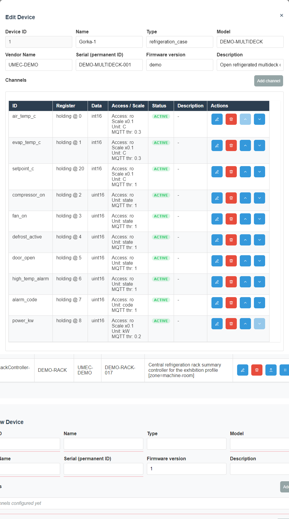
How to create a device step by step
In practical work the usual sequence is simple: configure the line first, then create the device, then add sensor channels and operator commands.
- Open Setup and select the target communication line.
- Enter line parameters such as baud rate, parity, stop bits, and polling interval.
- Save the line and confirm that communication is stable.
- Create a new device or open an existing one for editing.
- Fill in the device identity fields: name, address, and line assignment.
- Add channels for all required sensor and telemetry values.
- Add commands if the operator must control the device from the interface.
- Save the device and verify the result in Control.
What the line fields mean
- Line name A readable label that helps the operator distinguish one bus from another.
- Baud rate The communication speed. It must match the field devices on that line.
- Parity The parity mode. A wrong setting often breaks communication completely.
- Stop bits The stop-bit count. It must also match the devices on the bus.
- Polling interval How often the line is queried. Too fast can overload the bus, too slow makes data feel stale.
What the device fields mean
- Name The label shown to the operator in lists and on Control.
- Address The Modbus address of the device on the selected line.
- Line The physical or logical bus the device belongs to.
- Description Extra context for people, such as room, role, or equipment type.
- Template A shortcut when several devices share the same structure.
How to add registers for sensors
Every measured value is usually represented by a channel. The channel tells the system which register to read, how to interpret the raw data, and how to present the result to the operator.
Channel editor
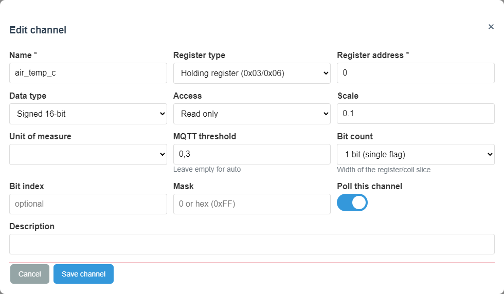
- Channel name A readable label such as "Supply temperature".
- Register type For example holding or input. It must match the device documentation.
- Register address The exact address in the device register map.
- Data type Defines how the raw register value becomes a number.
- Scaling Converts raw data into engineering values, for example 253 into 25.3 C.
- Units Makes the value understandable on Control and dashboards.
How to add commands
A command is needed when the operator must do more than read data: start, stop, acknowledge, reset, or switch a mode.
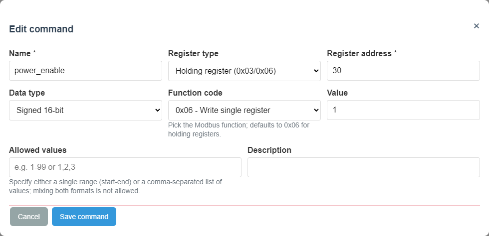
Command editor
Command result in Control
- Command name Should clearly describe the action, such as "Start pump" or "Reset alarm".
- Target register The register that receives the control value.
- Write value The exact value sent when the command is executed.
- Confirmation The result should be checked through visible state change in Control, not only by button press.
How to know the device definition is correct
- The device appears in the list under a clear name.
- Channels show real updating values.
- Labels and units are readable to the operator.
- Commands appear only where needed and produce the expected result.
When Scanner is useful
Scanner is not required in every project. If the site is already well documented and all addresses are known, devices may be entered directly. But where there is uncertainty, Scanner can save a lot of time.
sequenceDiagram
    participant O as Operator
    participant S as Scanner
    participant L as Line
    O->>S: Start scan
    S->>L: Check addresses and line behavior
    L-->>S: Return responses
    S-->>O: Show found devices
    O->>O: Import the required devices
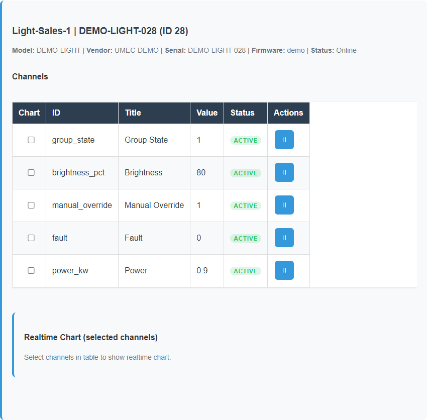
Step 7. Confirm that values are actually arriving
This is the key checkpoint. If a device exists in the list but its values are empty or not updating, commissioning is not finished yet.
A correct result looks like this: the device is visible, values are being read, and commands behave as expected when used.
What not to do too early
- Do not enable outside integrations before local operation has been confirmed.
- Do not begin with complex scenarios before basic telemetry is known to work.
- Do not jump into manual file edits if the same task can be done through normal configuration pages.
How to know commissioning is done
Commissioning can be considered complete when four simple statements are true:
- you can log in to the web interface reliably;
- network and time are set correctly;
- the required devices are visible and responding;
- current values appear on screen without confusion or uncertainty.
Completion in each mode
| Mode | What counts as complete | Where to check |
|---|---|---|
MQTT_DISABLED |
Local Control, Dashboards, Scenarios, and logs show a clear picture without outside connectivity. | Control, Dashboards, Scenarios, Scenario Log, Modbus Log, Storage. |
UMEC_SPACE |
Local operation is proven, then the site is visible in UMEC Space: dashboards, mobile screens, alerts, notifications, and allowed commands are configured for the project. | Settings -> Mode/Integration, top status row, UMEC Space Dashboard, the platform page, UMEC Home, or UMEC Business. |
MQTT_GENERIC |
Local operation is proven, the broker receives published data, and commands arrive on the expected subscribe topic. | Settings -> MQTT, Integration, MQTT broker logs, gateway runtime status. |
Commissioning examples
These examples follow the usual order on site: first access, line and device setup, and then the first healthy live values.
Login
Device setup
Live values

Related reference pages
- UI Reference for screen-by-screen meaning and screenshot-driven explanations.
- Template Formats for device, channel, command, and JSON structure details.
- Operations for everyday monitoring and command use after commissioning.