How to use this section
Workflow chapters explain where to click. This section explains what the edited entities actually are. Use it when the main question is not "which page should I open?" but "what does this object, field, register, command, or JSON block mean in practical operator terms?".
What will be documented here
The embedded interface allows the user to work with structured device definitions, channel/register descriptions, command definitions, and other operator-visible payloads. This page explains those shapes using realistic examples from the configured system.
Format groups
Device objects
Identity fields, address or unit id, titles, model references, and operator-facing metadata.
Channels and registers
Register type, address, data type, meaning, engineering interpretation, and visibility in Control.
Commands
Command identity, function, target register, value semantics, and when the command becomes available.
Templates and raw JSON
How reusable patterns differ from one-off editing, and when raw JSON should be used carefully.
Explanation model for every field
- what the field is called in the UI;
- what the field means;
- what values are common or recommended;
- what other fields it depends on;
- what the operator will later see in the interface because of that field.
Entity map
Device object
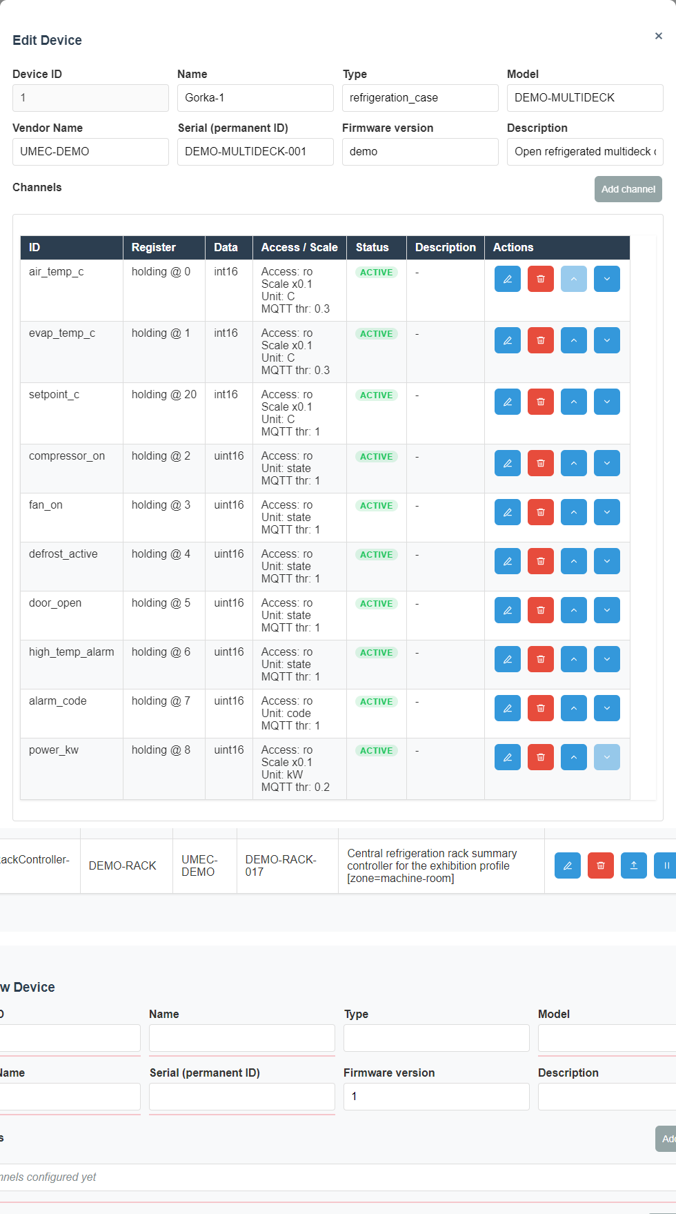
The device object is the root operator entity for a real Modbus node. The detailed walkthrough must explain naming fields, bus selection, address or unit id, profile or template linkage, visibility metadata, and how save behavior affects later polling and Control-page visibility.
- identity fields explain how the operator distinguishes two devices of the same model;
- transport fields explain which line or network path the device belongs to;
- profile fields explain whether the device follows a reusable template or custom definition;
- operator labels explain how the device later appears in lists, cards, and dashboards.
- Name The main human-readable identifier of the device in the interface.
- Address The Modbus address of that node on the selected line.
- Line Defines which communication path is used to poll the device.
- Description Extra context for operators, such as room, role, or equipment type.
- Template Speeds up setup when the same structure is reused.
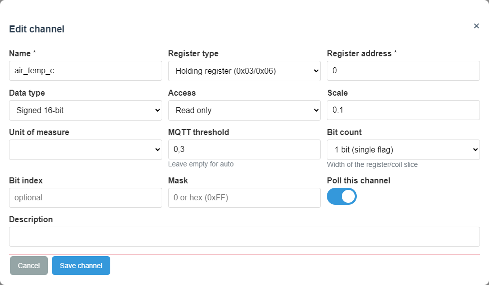
Channel and register entry
Channel definitions connect low-level register addresses to human-readable values. This reference must explain register family, address, data width, scaling, signedness, engineering units, visibility flags, and whether the value is intended for read-only monitoring or operator interpretation.
- Setup coverage must show where the channel is created and edited;
- Control coverage must show how the same definition becomes a visible live value;
- diagnostic notes must explain what stale or empty values usually mean.
- Channel name The label shown to the operator on Control.
- Register type Defines which register family is used.
- Register address Points to the exact location in the device map.
- Data type Defines how the raw value becomes a number.
- Scaling Converts raw data into engineering values.
- Units Makes the reading understandable without extra explanation.
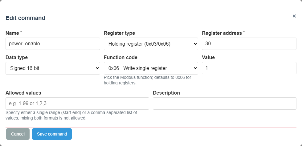
Command entry
Command definitions connect a visible operator action to a write or action-oriented Modbus operation. The detailed guide must explain target register semantics, write value semantics, optional confirmation expectations, and what visible effect the operator should expect after execution.
- Command name Should clearly describe the action.
- Target register Defines where the control value will be written.
- Write value The exact value sent to the device.
- Expected effect The state change the operator should later see on Control.
Template object
Templates exist to reduce repeated manual setup. The operator guide must explain when to start from a template, when to fork or customize it, and when direct JSON editing is too risky compared with structured UI editing.
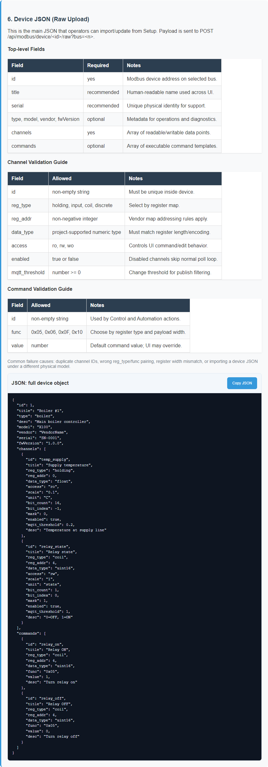
Raw JSON payloads
Raw JSON is where support and advanced commissioning work often becomes powerful but dangerous. This page family must explain object boundaries, stable keys, human-editable regions, and the warning signs that mean the user should stop editing manually and switch back to validated UI forms.
For UMEC Space, use the gateway device model JSON export. Upload this file to UMEC Space Dashboard under Models; it appears on the platform as a Custom Model. After that, the platform can map sensor telemetry and control commands from the gateway to the readable device model.
Why configuration dependencies matter
- how bus selection changes where a device can communicate;
- how line settings influence later online or offline behavior;
- how channel scaling and type choices affect Control and dashboards;
- how command definitions depend on the device transport and register model;
- how templates interact with custom per-device overrides.
- how model JSON exports become Custom Models in UMEC Space Models.
Examples on this page
Device object
Channel
Command
JSON reference
Reading order
- Device object reference
- Channel and register reference
- Command reference
- Template and raw JSON reference
- Cross-links back into Setup, Control, Storage, and Diagnostics
Short device creation sequence
- Configure the communication line.
- Create the device and enter its name and address.
- Add channels for measured values.
- Add commands for control actions.
- Verify the result in Control.